
How to Use a Visual Fault Locator
November 9, 2026
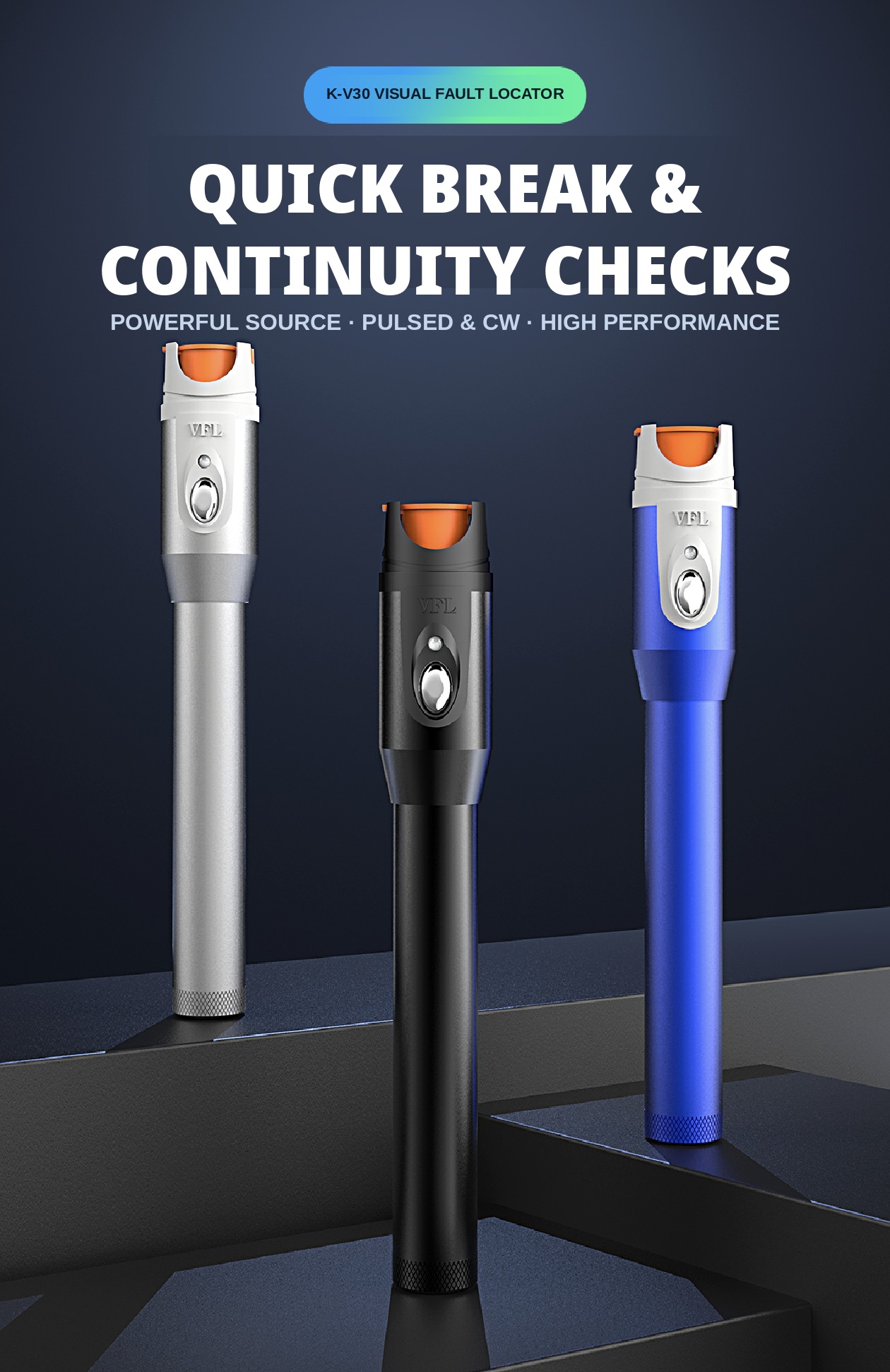
A visual fault locator (VFL) is the first tool out of the bag when a fiber link misbehaves. It launches bright red light — 650 nm — into the fiber, and wherever the light escapes, you can see it: a break glows, a bend that is too tight leaks a red halo, a poor connector shines at the joint. No trace to interpret, no settings to speak of — the fault shows itself.
This guide explains how to work a pen-type VFL properly: what the light finds and what it cannot, how to choose an output power, and how to keep the pen accurate. It is written around the K-V30, a metal-bodied pen VFL, and the checks apply to the VFLs in the fiber test equipment range generally. Browse that range as you read.
What the red light shows you
The principle is simple: light travelling down a healthy fiber stays inside it. At a fault, some of it escapes through the jacket — and at 650 nm, escaped light is plainly visible, even in a lit equipment room.
- Breaks. A broken fiber ends in a bright red glow at the break point. On a patch lead or drop cable this is usually the whole diagnosis: the link is dead, and here is exactly where.
- Sharp bends. A fiber bent tighter than it should be — pinched behind a panel, kinked at a tray edge — leaks light at the bend. The halo marks a loss point that a power meter would only report as a number for the whole link.
- Bad connections. A cracked ferrule, a poorly seated connector or a damaged mechanical splice glows at the joint, separating a connection problem from a cable problem.
- Identification. Light one fiber at the near end and its far end glows: the quickest way to confirm which lead in a bundle is which, and whether a lead is continuous at all before you plug it into anything live.
What a VFL does not do is measure. It gives no loss figure and no distance readout — for that you need a power meter for the number and an OTDR for the location along the span; see how to choose an OTDR. The VFL's job is the fast, visual first pass: find the fault you can see, fix it, then prove the link with instruments.
Choosing the power: 5, 10, 20, 30 or 50 mW
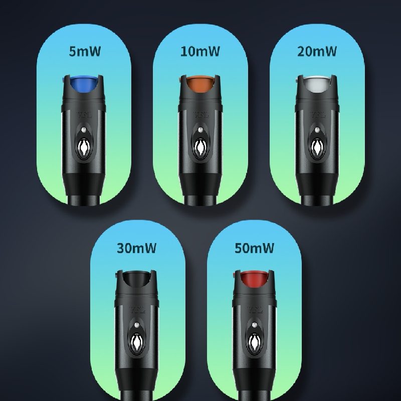
The K-V30 is supplied in one of five fixed output powers, chosen when you order: 5, 10, 20, 30 or 50 mW. Output power decides how much light reaches the fault — and how visible the glow is when it gets there. The choice is about the longest link the pen will actually check:
- 5–10 mW covers panel and rack work: patch leads, distribution frames, short jumpers. The glow sits close to the fault, which is what you want when fibers are bundled tightly together.
- 20 mW is the general field choice for drop and distribution work — brighter at the fault after the light has passed bends and joints along the way.
- 30–50 mW is for the longest runs a pen is asked to check, where the light has to survive the whole link and still show clearly at a break near the far end.
More power than the job needs buys glare, not answers: on a short lead, a very bright source lights the jacket along its length and the fault stops standing out. Pick the power for the longest link in your work, not the largest number on the list.
Using the K-V30, step by step
- Clean the connector first. A dirty end face scatters the light before it enters the fiber and weakens everything downstream. The routine is in wet-to-dry fiber end-face cleaning.
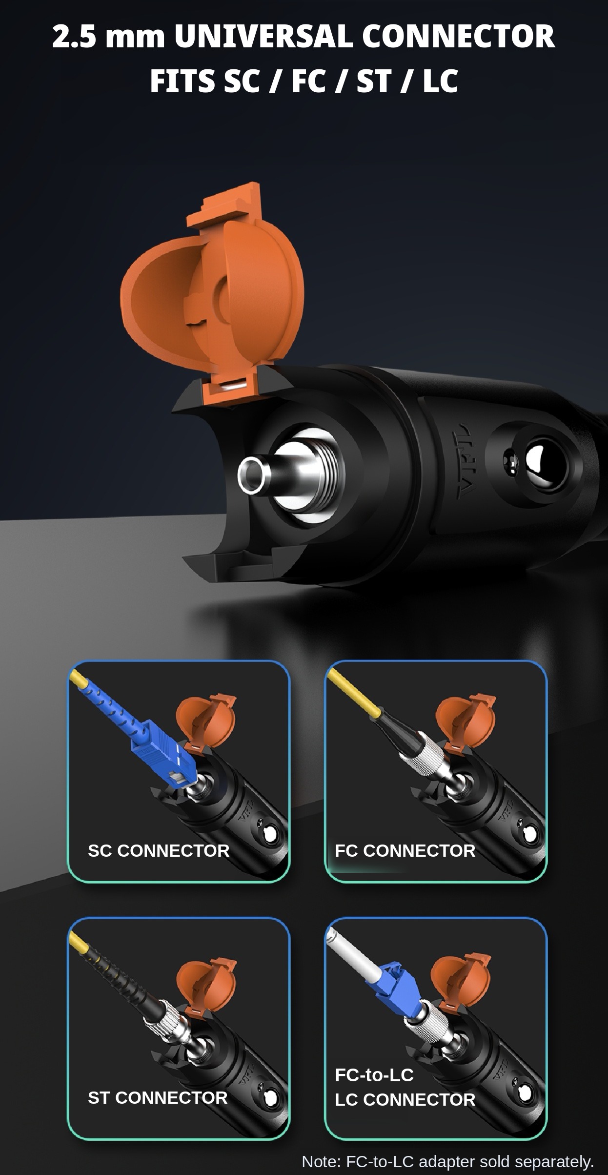
- Plug the fiber in. Flip open the dust cap and push the connector into the 2.5 mm universal port until it seats.
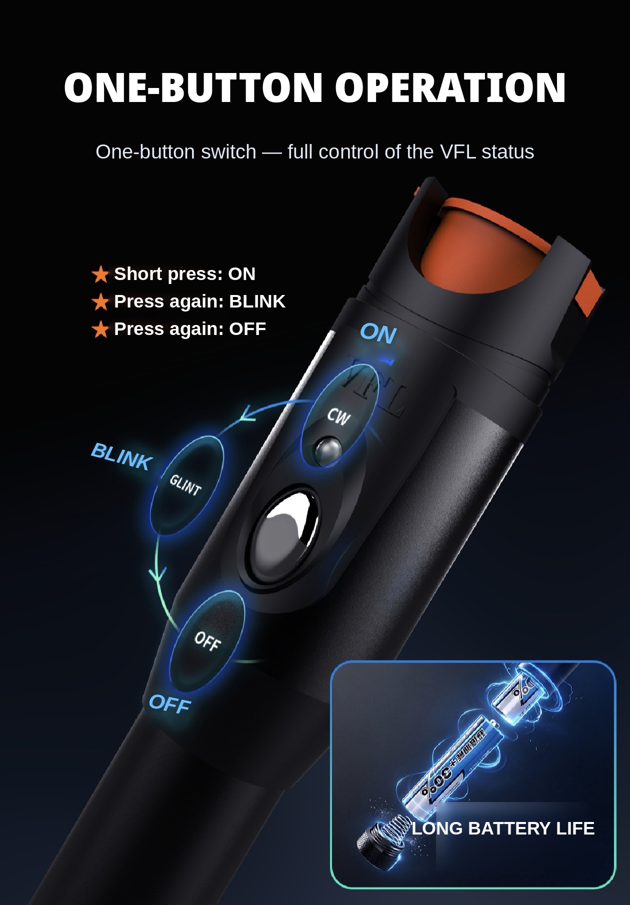
- Short-press the button once. The pen starts in CW mode — continuous red light.
- Walk the link. Follow the fiber with your eyes: a steady glow at a bend, joint or break point is the fault.
- Press again for blink. The light flashes. A blinking glow is easier to pick out on a crowded, lit panel — and it is the mode to use when a second person is watching the far end for identification.
- Press again to switch off, and close the dust cap before the pen goes back in the pouch.
One safety rule, without exception: never look directly into the beam, and never look into the end of a fiber that has a VFL connected to it.
One port for FC, SC and ST
The K-V30's port is a 2.5 mm universal connector: FC, SC and ST ferrules plug straight in, with no adapter to lose. LC connectors use a 1.25 mm ferrule, so LC work needs an FC-to-LC adapter — a small separate part, sold separately. Everything else about the check is identical.
Built for the tool bag
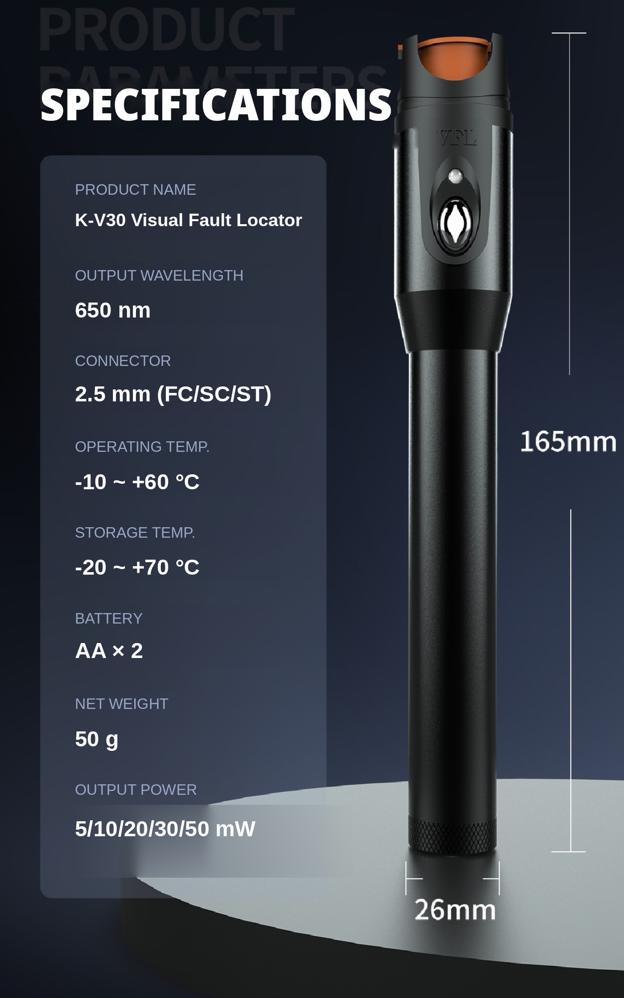
A VFL lives in a pouch, a pocket and a van footwell, and the K-V30 is built for that life. The pen body is aluminum alloy — non-slip in the hand and corrosion-resistant — at 165 × 26 mm and 50 g. Bodies come in silver, black and blue, and the flip dust caps come in a range of colours, with custom cap colours supported: handy for telling several pens apart at a glance, and for matching a fleet to a customer's own colours.
The working parts are tested the way they will be used. The button is rated by a 100,000-press test, and every finished pen is break-tested after assembly — run against fiber and checked — before it is packed and shipped. Power comes from two AA batteries, with long runtime; when they finally fade, replacements are the most common battery on earth.
When the tip wears: replaceable head and ferrule
The part of a VFL that wears is the part the connectors touch. On the K-V30 the metal head (2.5 mm) and the ceramic ferrule (7 mm) behind it are user-replaceable: the head comes off and the ferrule swaps out, so a worn or damaged tip is a spare part, not a new pen. If the output looks weak on a fiber you know is good, suspect the ferrule first.
Two habits keep the tip alive longer: close the dust cap whenever the pen is not connected, and treat the ferrule like any other end face — keep it clean. Note that the ceramic ferrule is a wear part and is not covered by the warranty; that is exactly why it is made replaceable.
K-V30 specifications
| Item | Specification |
|---|---|
| Model | K-V30 visual fault locator (pen type) |
| Output wavelength | 650 nm |
| Output power | 5 / 10 / 20 / 30 / 50 mW (choose when ordering) |
| Output modes | CW (continuous) and blink, cycled by one button |
| Connector | 2.5 mm universal — FC / SC / ST direct; LC via FC-to-LC adapter (sold separately) |
| Body | Aluminum alloy, in silver, black or blue |
| Battery | 2 × AA |
| Dimensions | 165 × 26 mm |
| Net weight | 50 g |
| Operating temperature | −10 ~ +60 °C |
| Storage temperature | −20 ~ +70 °C |
What's in the box
- Visual fault locator pen
- Cloth pouch
- Anti-drop wrist strap
- AA batteries
The short version
Clean the connector, plug in, one press for continuous light, a second press for blink when the panel is busy. Pick the power by the longest link you check — 5–10 mW at the panel, 20 mW in the field, 30–50 mW for the longest runs — keep the dust cap closed, and when the tip wears, replace the ferrule instead of the pen.
Tell us how your crews use VFLs — the links they check and the connector mix — via the contact form on this site, by email at [email protected] or on WhatsApp at +86 150 6823 2998, and we will confirm the right K-V30 power for your work. The pen sits in the fiber test equipment range alongside the switchable-power K-V10 visual fault locator and the flat-bodied K-V20 visual fault locator — three ways to put a red light on a fault, for three kinds of job.